
| AVSR3 Triple Switch Autocalibrating Variable Step Power Factor Regulator |
| Site Map | Home | All Products | Process Control & Automation | Power Factor Technology Overview |
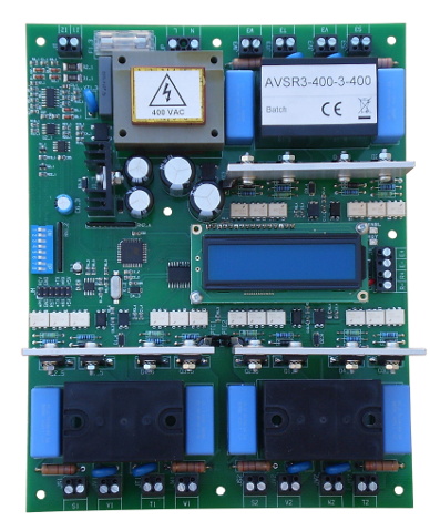
The AVSR3 employs our variable step technology to compensate reactive current in seven steps. It features three 25 A solid state switches to connect three autodetected compensating capacitor banks in and out of the single- or three- phase line system. At installation no adjustments are required as each capacitor size and all other operation parameters are detected automatically making AVSR3 commissioning purely "wire-up-and-play".

AVSR3 Autocalibrating variable step PF regulator |
The variable step technology provides for different capacitor banks of any size to correct power factor in practically any arbitary minimum step and correction range size. At every sampling instant, the controller calculates the required compensation step and connects or disconnects a combination of banks whose sum is equal or closest to the calculated step value. In the AVSR3, three banks are used and, if sized as x1, x2 and x4 multiples of the smallest required step, provide seven steps of compensating operation. Switch activation/deactivation happens at every sampling instant as set at the DIP switch between 5 and 30 seconds. The AVSR3 response time range makes it particularly suitable for dynamic power factor compensation of frequently started, low-duty or variable loads such as:
Each capacitor bank size is autodetected during AVSR3 installation. The unit features a selfcalibrating function during which the AVSR3 corrects all internal errors and offsets, measures the current transformer phase shift and the individual capacitor bank sizes. The measured parameters are then used during normal operation ensuring accurate, effective and dependable performance. Following autocalibration no other adjustment is required making AVSR3 installation fast and error-free. |
The AVSR3 is highly integrated and adaptable to all power factor capacitor compensation applications. The only other parts required to build a complete power factor correction system are the current transformer, the compensating capacitors and their protective fuses.
The AVSR3 is designed for standard European and US, single- and three-phase, 50-60 Hz lines. Characterizing features are as follows:
During normal operation the AVSR3 display indicates system status, error conditions (such as out-of-range line frequency or an overheated switch) and variables such as load/line power factor and power, percentage capacity switched-in and switch state. In the event of a power circuit overheating, the failing switch and the "Ready" output are deactivated until power is removed. Overheating is usually the result of switch bypass relay failure and, more rarely, thyristor short failure.
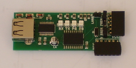
| The controller can be programmed, configured and monitored by computer using the USB/TTL interface and the provided avsr3_jobs software, downloaded from here (760K, zip archive). |  |
Our power factor related products are summarized here with sampling/small quantities being available for online purchase here.
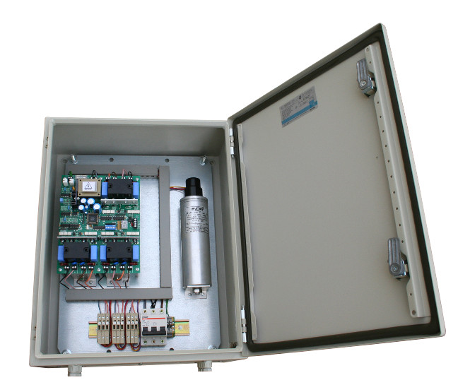
| Assembled, ready-to-install power factor correction systems in wall mountable or free standing cabinets are available on a custom basis. | 
|
| Back to top | Site Map | Process Control & Automation | All Products | Power Factor Technology Overview |